Customer Login
Swansea Tribology Services
  • Home
  • News
  • About
    • About Us
    • Oil Analysis
    • Condition Based Maintenance
    • Recruitment
  • Services
    • Insulating Oil Analysis
    • Lubricating and Hydraulic Oil Analysis
    • Grease Analysis
    • Fuel Analysis
    • Failure Investigation
    • Water Analysis
    • Cutting Oils And Metal Working Fluids
    • Power Stations
    • Heavy Industry
    • Wind Power
    • Oil & Gas, Mining
    • Marine
    • Manufacturing
    • Transport
    • Service Industry
    • Filtration Services
  • Bottles
  • Knowledge Base
    • New Customers
    • Shipping
    • Taking Samples
    • Interpretation
    • Web Database
    • Condition based Maintenance/Monitoring
    • Actions
    • FAQ
    • Downloads
  • Contact Us

Power Stations

Where the cost of failure is deeply felt.

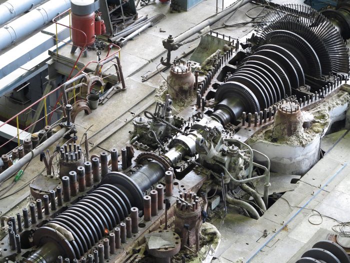
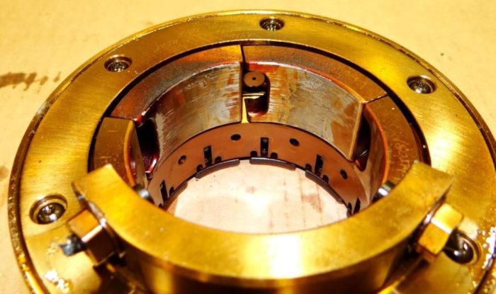
Turbine oil systems are vast and lubricants are expected to keep going forever. The list of possible problems is also impressive. New oil formulations bring potential for longer lubricant life, but not without risks. The key issue is varnish. Solubility characteristics of new lubricants, remnants of old Group I oils, poor demulsification or air release can all contribute. Our suite of tests for oxidation stability and varnish control will help ensure smooth operation without unnecessary trips and costly downtime.

If all of this seems too daunting and complicated – don’t worry – there is help at hand. We can help tailor your testing regimen based on ASTM Practice D4378, which proposes testing programmes for a range of different scenarios, including new oil deliveries and lubricant changeover. Thoughtful monitoring can ensure lubricant does not degrade prematurely and prevent failure.

Once you are ready to proceed please go to our Welcome page to get started or get in touch.

Service Categories

  • Insulating Oil Analysis
  • Lubricating and Hydraulic Oil Analysis
  • Grease Analysis
  • Fuel Analysis
  • Failure Investigation
  • Water Analysis
  • Cutting Oils And Metal Working Fluids
  • Package B - Cleanliness
  • Varnish and Oxidation
  • Transformer Oils
  • Wear Debris Analysis And Additional Tests

This suite comprises all of the tests present in Package A and adds the determination of the oil’s cleanliness as described by the ISO Cleanliness Code. This package is the routine suite for hydraulic and turbine oils, as well as for any systems where high cleanliness levels are required. It adds a lot of detail about the types of wear particles and contaminants in the oil. Together with PQ Index and Elemental Analysis it delivers a comprehensive overview of the wear situation.

Viscosity

Viscosity is a measure of fluids resistance to flow. Often defined as an ISO or SAE viscosity grade (such as VG 220 or SAE 15W/40). Typically measured at 40 or 100ºC. Each application will have a viscosity range suited to the task. Too high a viscosity can lead to lubricant starvation, wear in circulating pumps, increased temperatures and reduced efficiency. If viscosity is too low, the components will not be sufficiently separated resulting in excess friction and causing wear on the machinery. A change in viscosity could be due to:
  • Contamination with water/fuel/solvents/very small particles
  • Oxidation or ageing of the oil
  • Incorrect oil
  • Mechanical shearing of the oil

Acidity or Total Acid Number

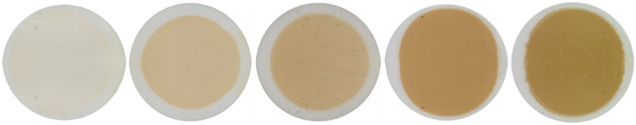
Oil oxidises over time and becomes more acidic indicating the age of the oil. If the oil is too acidic it can damage metal components and further accelerate the ageing process. A rapid increase in the Acid Number may be due to:
  • Severe oxidation (often caused by overheating)
  • Depletion of additive package
  • Top up with a large volume of incorrect oil with a much higher base acidity e.g. hydraulic oil
  • Contamination with process fluids; or in case of engine oils with combustion products
 

Particle Quantifier Index (PQ)

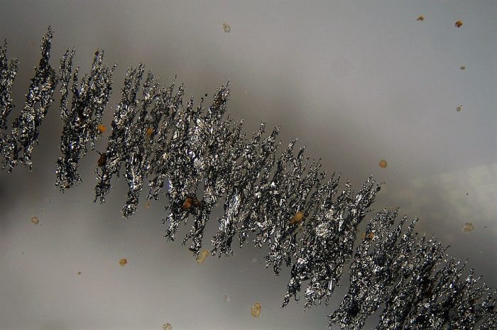
  • A measure of total magnetic ferrous debris in the sample irrespective of particle size.
  • Does not detect non-magnetic ferrous debris e.g. rust.
  • Combine with Elemental Analysis and ISO Code for comprehensive assessment of the wear situation.

Elemental Analysis

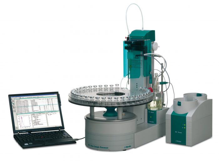
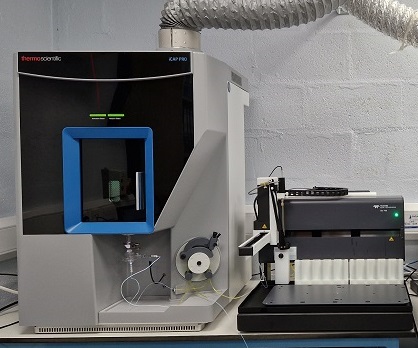
Induction Coupled Plasma Optical Emission Spectroscopy (ICP-OES) is used to measure the concentration of over 20 different elements in the oil. These include wear metals, additives and contaminants. We have recently upgraded our instrument - you can read about some of the resulting improvements here.

By monitoring wear metal concentrations the wear rate and its origin can be established. Trending additive levels ensures that the right oil is used and that it remains suitable to the task, while measuring levels of contaminants helps prevent severe wear and loss of function.

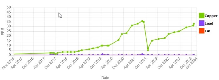
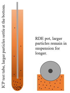
For grease and debris samples a combination of a Rotating Disk Electrode Optical Emission Spectrometer (RDE) and an ICP-OES is used. The RDE eliminates a lot of cross-contamination issues and, as no dilution with solvents is required, allows for more accurate measurement of heavily contaminated samples which would settle at the bottom of the test tube if an ICP-OES was used. The ICP-OES is then used to cover elements not measured by the RDE (mostly additives, although the wear metals are also measured). The ratio of RDE to ICP wear metal levels gives an indication of wear particle sizes.


Water Content

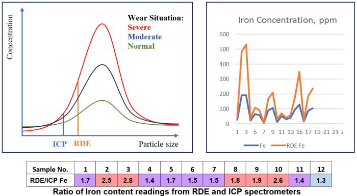
Excess water in the oil reduces the lubricating effectiveness by disrupting the oil film, accelerates corrosion (i.e. rusting of iron and steel surfaces), depletes and/or degrades additives and accelerates the aging (oxidation) of oil.  Where large quantities of water are present oil may become emulsified. The emulsions can combine with insoluble oxidation products to form sludge which impairs the operation and reliability of equipment. In addition excessive water if present as free water can promote bacteria growth or form hard deposits on bearing surfaces.

An increase in water content may be due to:

  • Leaking covers on equipment
  • Leaking oil coolers
  • Excessive leaking turbine gland steam seals
  • Condensation
  • Using water contaminated fluid for topping up
 

Particle Counting

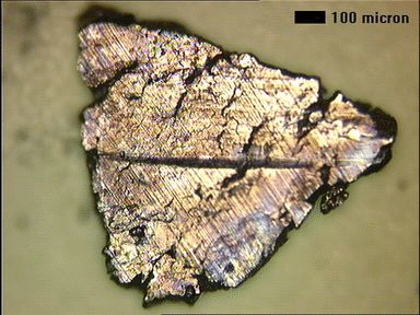
Fluid cleanliness is particularly critical for hydraulic and turbine oils. High levels of particulates, especially if the particles are abrasive (e.g. silica), can increase wear of components and lead to reduced life and premature failure. It has been demonstrated that improving cleanliness by even a couple ISO Codes can lead to doubling of the expected life of a component. Conversely, contaminated lubricant will greatly reduce component lifespan and increase costs. 
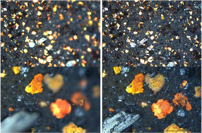
Fluid cleanliness is quantified by counting particles in prescribed ranges of particle sizes. It is typically expressed using an ISO 4406, a NAS 1638 or an SAE AS4059 cleanliness code. There are several ways of obtaining the particle count with the most common being instrumental particle counting and the patch test method.

Instrumental Particle Count

Most instrumental particle counters relate a change in the amount of light (either visible or laser) transmitted through the fluid into a particle count using a stored calibration. When a particle flows between the light source and the sensor, the measured output drops and this is interpreted as a particle of a certain size. Some instruments scan over a particle and are able to capture its shape and outline. Other systems measure a pressure drop as the oil is passed through a series of sieves.

Patch Test

Another approach is to pass the fluid through a filter membrane and with the aid of microscopy to either count the deposited particles or perform a comparison with reference slides. The advantage of the latter approach is that, as well as obtaining the ISO Code, the types of wear and contamination particles can be examined and captured, giving further insight into the types of wear or contamination. This method is also insensitive to air bubbles and water droplets, which can interfere with the readings of the instrumental particle counters. An example of such patches can be seen in the slideshow. At STS we have invested in a new state of the art Leica motorised microscope and camera system with a range of illumination options. We are particularly excited about Darkfield Illumination - a way to light up the patch from all sides and get better definition of difficult slides and translucent contaminants in particular. 
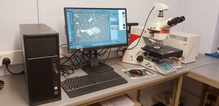
We are also enjoying the Z-stack feature - it combines in-focus areas from multiple images to achieve a single fully focused composite as shown below. The overview/tile stitching facility lets us construct overviews of an entire membrane or ferrography slide. In the following overview we were able to use Dark Field illumination to successfully separate translucent particles from the woven 11µm membrane patch, which is also translucent. 
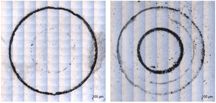
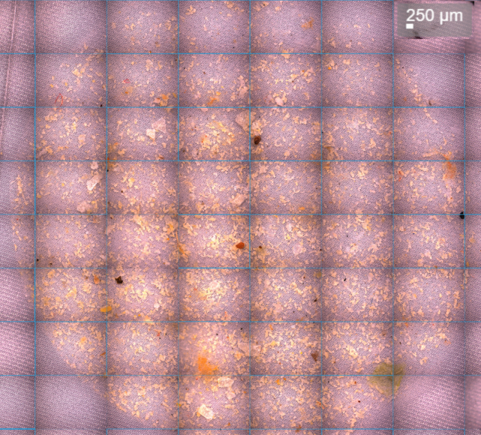
The following overviews show differences in large (inner ring) and fine (outer ring) particle densities in two ferrography samples.

Varnish is the sticky residue created by the decay of both mineral and synthetic lubricants. Although it can cause a variety of problems there are solutions for monitoring and controlling oil degradation and varnish formation.

Varnish and Membrane Patch Colorimetry

Varnish

Varnish is the sticky residue created by the decay of both mineral and synthetic lubricants. If left unchecked it can bring the entire operation to its knees. It can cause premature failure, erratic operation and can be the cause of a costly shut down. There are many signs of varnish build-up, including sticky valves, overheating bearings, decreased effectiveness of heat-exchangers, blocked filters and reduced lubricant life. A way of detecting build-up of varnish and its precursors early is through Membrane Patch Colorimetry.

The test is a reflection of both the solubility of the oil and the amount of varnish precursors in the lubricant. Different types of lubricant (e.g. Group I and Group II) have different solubility properties and are able to mobilise degradation products to a different degree. This means that some oils degrade more rapidly but are better able to maintain degradation products in solution preventing varnish build up. Others have better oxidation stability but at the cost of poor solubility - even relatively small quantities of varnish precursors may result in varnish deposits. Things get even trickier when a Group I lubricant is replaced with a Group II oil! This also means that a simple oil change is rarely sufficient to eradicate varnish problems.

It doesn't help that varnish does not deposit uniformly throughout the system. Regions with high local pressures are at risk as are the low flow areas, especially if the oil has cooled after passing through some exposed pipework or after a shutdown. This temperature sensitivity means that seasonal variations and interrupted operation make diagnosing varnish even trickier.

Whatever your situation, monitoring varnish potential through Membrane Patch Colorimetry will help you stay in control.

Membrane Patch Colorimetry

MPC Color

As the solubility of a lubricant varies with both temperature and time, the test procedure includes a heat and rest cycle. This is used to standardise each measurement and ensure consistent comparisons can be made with every sample. After the heat and rest cycle the lubricant is mixed with a solvent and filtered through a fine membrane filter. The shading of the membrane patch is then measured with a colorimeter to determine the varnish potential value.

If the measured MPC/VP value is high, varnish mitigation technologies can be employed to clean up the system. Varnish precursors are very fine sub-micron agglomerations of oxidation products and can pass through conventional filters, although when the oil is saturated they can cause filter blockages. Therefore special filtration technologies aimed at removing the fine sub-micron contaminants need to be utilised. Such technologies include electrostatic filtration, depth media filters and the electro-physical separation process to name but a few. Each comes with its own strengths and weaknesses and should be considered carefully depending on specific application. Membrane Patch Colorimetry

Membrane Patch Colorimetry

Oxidation Stability - RPVOT

A key property of the oil is its oxidation stability – that is, its ability to resist oxidation.

A standard measure of this property is the Rotating Pressure Vessel Oxidation Test (RPVOT, formerly RBOT, ASTM D 2272). The test presents a simulated worst case scenario, where an oil sample is subjected to the harsh conditions of high temperature and high pressure oxygen atmosphere in the presence of water and a copper catalyst. As oil oxidises oxygen is consumed and the pressure drops. Time taken to achieve a specific drop in pressure is then recorded.

By monitoring the RPVOT value of a lubricant its remaining useful life can be assessed. Note however, that while this test was very useful for assessing Group I oils, which age in a fairly predictable manner, with Group II oils things get a little trickier. Many of the modern synthetic lubricants achieve more than 1000 minutes in the RPVOT test. However, for some oils this is the result of the additives inhibiting the copper catalyst. As a result, the RPVOT value measured will stay very high until the additives have depleted, at which point it may reduce rapidly.

It is therefore prudent to augment the RPVOT test by also monitoring levels of the anti-oxidant additives. For that we can rely on the RULER test.

Remaining Useful Life Evaluation Routine (RULER)

Remaining Useful Life Estimation Routine (RULER) uses Linear Sweep Voltammetry to measure the levels of Amine and Phenol anti-oxidant additives in the oil. These are typically compared with a baseline measurement obtained from a virgin oil sample (ideally from the same batch of oil). If anti-oxidants are allowed to deplete below a critical level the oxidation process accelerates, leading to reduced oil life and potential for varnish deposition. RULER monitoring enables management of the additive levels through top up or partial changes, significantly extending the life of the oil.

FTIR Spectroscopy

Fourier-transfer Infra Red Spectroscopy (FTIR) is a powerful tool for analysis of oil, grease and fuel samples. It is especially useful for monitoring and identifying certain types of contaminants.

The underlying principle is that infrared energy from the source is absorbed in the sample at  wave lengths which are characteristic of specific molecular bonds. Each scan generates an FTIR spectrum which can be analysed and interpreted.

At its most basic the technique can be used to measure predetermined parameters, such as oxidation, nitration, sulphation or presence of fuel and glycol in an engine oil. Some of those require prior calibration and a scan of a virgin sample to be used as reference.

More advanced analysis can help monitor degradation, identify and match unknown contaminants, verify lubricant formulation or help identify and source an unknown lubricant.

In some cases Gas Chromatography coupled to Mass Spectroscopy (GC-MS) is called upon to work in tandem with FTIR analysis on particularly tricky samples, where exacting information is nonetheless required.

You can download an Example FTIR Report here


Just like lube oil analysis mentioned elsewhere a lot of value can be derived from transformer oil testing. The tests for dissolved gases and furfuraldehyde usually indicate the condition of the transformer whilst most of the other tests e.g. acidity, electric strength, fibres reflect the quality of the oil. Since it is not desirable to have any water present, that test can also indicate whether the dryers are functioning correctly.

Water Content (Oil Condition)

High water content will reduce the insulating properties of the oil, which may result in dielectric breakdown. It can cause breakdown of cellulose based paper insulations in the windings, together with accelerating corrosion.

Acidity (Oil Condition)

High acidity can result in corrosion and varnish deposits, together with degradation of oil and paper in the windings. Consequently, sludging can occur within the oil, thus reducing heat dissipation qualities of oil and causing overheating. Reduced insulating properties and an increase in water content normally go hand in hand with high acidity.

Electric Strength (Oil Condition)

Low electric strength indicates oil is no longer capable of performing the vital function of insulating under high electrical fields.  Poor electric strength is often linked with high water and fibre content.

Colour (Oil Condition)

An indication of level of oxidation and degradation of oil.

Fibres (Oil Condition)

Under high electric fields the behaviour of fibres can cause a dramatic reduction of insulating qualities of oil. Although invisible to the naked eye fibres are often introduced via poor maintenance techniques.

Polychlorinated Biphenyls (PCBs)

PCBs are insulating liquids used for their non-flammable properties, mainly in transformers, whether a fire would be unacceptable and as the dielectric in capacitates. Unfortunately the mineral oil used in transformers has become cross contaminated over the years. As PCBs are fairly non-biodegradable and tend to collect in food chains legislation was brought in to prevent wide-spread contamination. Liquids containing over 50 mg/kg must be classed as injurious substance and disposed of via costly high temperature incineration. It is therefore essential those responsible for plant know their level of contamination and have strict controls on oil movements to site.

Dissolved Gas Analysis (DGA) and Buchholz Gas Analysis

This is the single most important test performed on transformer oil and is used to determine the concentration of certain gases such as nitrogen, oxygen, carbon monoxide, carbon dioxide, hydrogen, methane, ethane, ethylene and acetylene.

The concentration and relative ratios of these gases can be used to diagnose certain operational problems and incipient faults in transformers, which may or may not be associated with a change in physical or chemical property of the insulating oil.

For example, high level of carbon monoxide relative to other gases may indicate thermal breakdown of cellulose paper while hydrogen in conjunction with methane may indicate a corona discharge. Acetylene is considered a significant gas generated as it is formed in breakdown of oil at temperatures in excess of 700oC and can indicate a serious high temperature overheating fault.


FFA (Furfuraldehyde)

This is a measure of the degradation of cellulose paper in the windings i.e. as the paper ages its degree of polymerisation (DP) reduces and thus so does its strength as it becomes more brittle. The DP of paper can directly related to the concentration of furan derivatives in the oil which are formed as a direct result of the breakdown of the polymeric structure of cellulose paper. New paper has a DP rating of 1250 while at 250 the paper is sufficiently brittle to fall away from the windings. It is therefore possible to use FFA to estimate the used life of the transformer as well as which will be dependent on factors such stresses on plant, overheating etc. FFA formation can also indicate low temperature overheating.

Metals in Oil

Elemental data helps to pinpoint the origins of faults for example iron and copper can be indicative of arcing between a copper contact and iron core.

We offer a range of techniques for extracting, separating and analysing wear debris from both oils and greases as well as oil filters. A wider range of additional tests is available. Large quantities of oil used in power station turbine systems make effective monitoring and management of oil quality a high priority.

Analytical Ferrography

Analytical Ferrography is a technique for depositing and analysing wear particles contained in an oil or grease sample. The sample is deposited onto a glass slide, with the particles trapped by strong magnets and the oil washed away with a suitable solvent. Both linear and rotary particle deposition systems exist. At STS preference is given to a rotary system, which has been developed at the company. It ensures good separation of particles over the three rings, with particles also being sorted by size with the larger particles settling out on the inner ring.
Once deposited the particles are analysed by a metallurgist, who is able to report on the relative quantities, types and sizes of particles present. A Particle Quantifier Index of the slide is also recorded. All of this is taken into account to produce a comprehensive report on the wear rate and situation.
You can find an example Ferrography Report available for download here.
We are now also able to supply Ferrography Slides.

Failure Investigation - Wear Debris

Depending on the failure mode (e.g. wear related or catastrophic failure due to overloading), there may be wear metal evidence present in the lubricant or in the oil filters. We are able to extract and analyse this wear debris through a collection of different analytical techniques. Extracted particles can be deposited on a filter membrane during the Patch Test or deposited on a glass slide to enable Analytical Ferrography. Elemental data can be obtained from bulk fluid analysis as well as from Scanning Electron Microscopy. The latter allows for individual particles to be interrogated and for data to be compared against machine metallurgy.  

Filter Debris Analysis

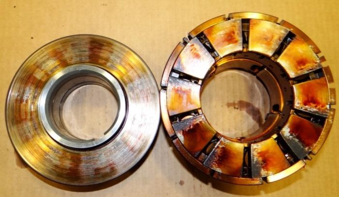
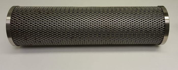
Oil filters are essential to maintaining oil cleanliness and removing wear metals and contaminants. As they perform their function, however, they also remove some of the information about wear and contamination levels from the oil stream. This is then stored in the filter itself. Fortunately Filter Debris Analysis grants us access to this store of information. By extracting and analysing the entrained particles we can learn a lot about the wear situation or the source of contamination. Oil filters come in many shapes and sizes and how we treat an individual filter will depend on its size and construction. Typically a section of the outer cage is cut out and removed to enable access to the filter media. 
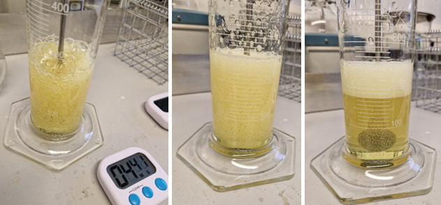
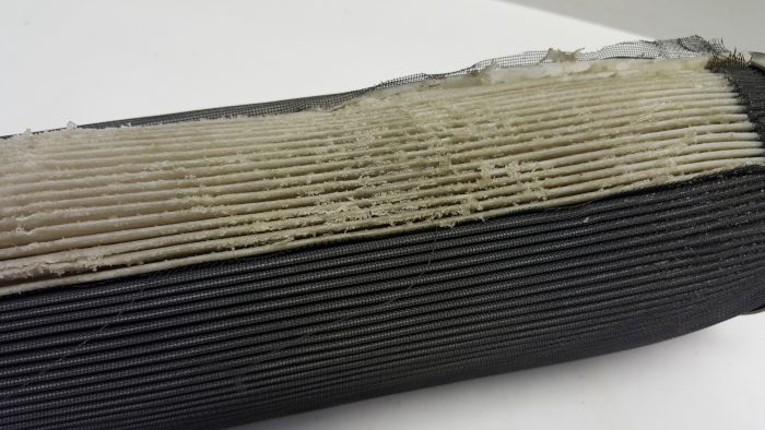
A section of the filter media is then removed and placed into a beaker. The beaker is then filled with solvent and an ultrasonic bath is used to agitate and extract the particles and any residual oil present. The solvent is then evaporated leaving the particulates and any residual oil. 
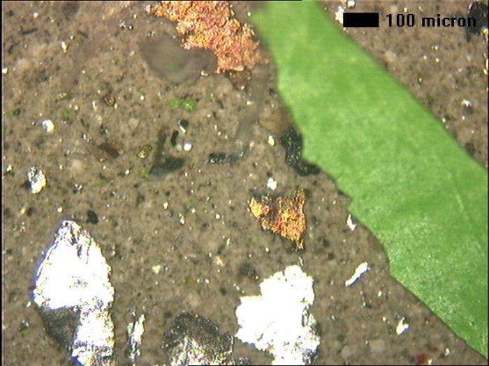
A portion of the debris is then deposited onto a filter membrane for microscopic analysis. The remaining oil/debris mixture is then analysed using a Rotating Disc Electrode Optical Emission Spectrometer to determine the elemental composition of the debris mixture. This gives a breakdown of the different wear metals and contaminants present. Where more detail is needed, the membranes containing the particles are analysed using a Scanning Electron Microscope with Energy Dispersive X-Ray facility. This provides information on the exact elemental composition of individual particles, which can then be matched to specific component metallurgies.

Failure Investigation - Component Testing

In addition to wear debris analysis we are able to review failed components and engage a select group of partners to deliver a comprehensive analysis. Techniques available include the initial visual inspection, sectioning and metallographic analysis, hardness testing, elemental analysis via SEM-EDX, etc.

Air Release

Air can be present in the oil in the following states: dissolved, entrained, free and foam. A certain quantity of dissolved air is normal - typically around 10% by volume for mineral oils. Suspended microscopic air bubbles in oil are described as entrained air and result in clouding of the oil. Entrained air can affect compressibility, heat transfer characteristics, oxidation, cavitation and varnishing (especially through microdieselling). Free air may be found in air pockets, which are most common in dead zones and high regions. It can impact hydraulic compressibility and lead to vapour lock causing starvation of oil supply and loss of control. Foam occurs when there is more than 30% air in the lubricant. Excessive foam can lead to poor lubrication, loss of control, poor heat transfer and accelerated oxidation. An oil's Air Release properties can be assessed via the ASTM D3427/IP313 test methods.
"Compressed air is blown through the test oil, which has been heated to a temperature of 25, 50, or 75 degrees C. After the air flow is stopped, the time required for the air entrained in the oil to reduce in volume to 0.2% is recorded as the air release time."

Foaming Characteristics

Foaming of lubricating oils is a relatively common issue. It is especially pertinent in applications involving turbulence, high speed gearing or high volume pumping, where it can lead to inadequate lubrication, cavitation, overflow or premature oxidation. Foaming can be countered by addition of anti-foaming additives (typically silicone compounds), however over-addition can lead to deterioration of the Air Release properties. The additives also deplete over time and should be monitored, together with the oil's foaming characteristics.

The test involves passing controlled quantities of air through the sample at specific temperatures. The amount of foam generated reflects the foaming tendency, while the amount left after specified settling time is the foaming stability. There are three test sequences (at 24, 93.5 and 24 degrees C for the same aliquot which underwent sequence II testing). The results are given for the three test sequences, and expressed as "Foaming Sequence I XXX/YYY", where XXX is the amount of foam generated and YYY the amount of foam after the settling phase, both are expressed in ml.

Typically Foaming Characteristics are measured to ASTM D892 or IP146.

Demulsification value

Demulsification value reflects the ability of the oil to shed water from an emulsion. It is commonly applied to turbine oils (especially steam turbines) and may also be relevant to other applications where there is a risk of oil/water emulsions forming.

The test involves passing steam through the test sample until the resulting water/oil emulsion doubles in volume. The sample is then maintained at a specified temperature and time taken for water to separate out of the emulsion is measured.

Demulsification Value is reported in seconds (<300 s is typically satisfactory, while values above 600 s may give cause for concern). If the sample failed to separate fully after 1200 s, the amount of oil in ml that has separated will be reported (e.g. "9 ml, where 20 ml is required for total separation).

The test is carried out to a procedure based on the IP19 test method.

FTIR Spectroscopy

Fourier-transfer Infra Red Spectroscopy (FTIR) is a powerful tool for analysis of oil, grease and fuel samples. It is especially useful for monitoring and identifying certain types of contaminants.

The underlying principle is that infrared energy from the source is absorbed in the sample at  wave lengths which are characteristic of specific molecular bonds. Each scan generates an FTIR spectrum which can be analysed and interpreted.

At its most basic the technique can be used to measure predetermined parameters, such as oxidation, nitration, sulphation or presence of fuel and glycol in an engine oil. Some of those require prior calibration and a scan of a virgin sample to be used as reference.

More advanced analysis can help monitor degradation, identify and match unknown contaminants, verify lubricant formulation or help identify and source an unknown lubricant.

In some cases Gas Chromatography coupled to Mass Spectroscopy (GC-MS) is called upon to work in tandem with FTIR analysis on particularly tricky samples, where exacting information is nonetheless required.

You can download an Example FTIR Report here


Coldharbour Farm Stables, Wood Street, Swanley, BR8 7PA


Unit 5, Penrice Court, Fendrod Business Park, Swansea, SA6 8QW

  • Copyright OAS 2025 - All rights reserved
  • Cookie and Privacy Policy
  • Website by NetBop