Fluid cleanliness is particularly critical for hydraulic and turbine oils. High levels of particulates, especially if the particles are abrasive (e.g. silica), can increase wear of components and lead to reduced life and premature failure. It has been demonstrated that improving cleanliness by even a couple ISO Codes can lead to doubling of the expected life of a component. Conversely, contaminated lubricant will greatly reduce component lifespan and increase costs.
Fluid cleanliness is quantified by counting particles in prescribed ranges of particle sizes. It is typically expressed using an ISO 4406, a NAS 1638 or an SAE AS4059 cleanliness code.
There are several ways of obtaining the particle count with the most common being instrumental particle counting and the patch test method.
Instrumental Particle Count
Most instrumental particle counters relate a change in the amount of light (either visible or laser) transmitted through the fluid into a particle count using a stored calibration. When a particle flows between the light source and the sensor, the measured output drops and this is interpreted as a particle of a certain size. Some instruments scan over a particle and are able to capture its shape and outline. Other systems measure a pressure drop as the oil is passed through a series of sieves.
Patch Test
Another approach is to pass the fluid through a filter membrane and with the aid of microscopy to either count the deposited particles or perform a comparison with reference slides.
The advantage of the latter approach is that, as well as obtaining the ISO Code, the types of wear and contamination particles can be examined and captured, giving further insight into the types of wear or contamination. This method is also insensitive to air bubbles and water droplets, which can interfere with the readings of the instrumental particle counters. An example of such patches can be seen in the slideshow.
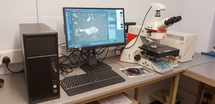
At STS we have invested in a new state of the art Leica motorised microscope and camera system with a range of illumination options. We are particularly excited about Darkfield Illumination – a way to light up the patch from all sides and get better definition of difficult slides and translucent contaminants in particular.
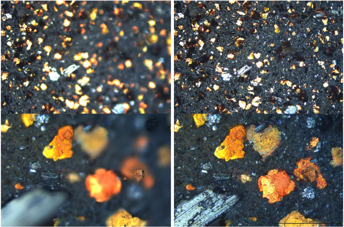
We are also enjoying the Z-stack feature – it combines in-focus areas from multiple images to achieve a single fully focused composite as shown below.
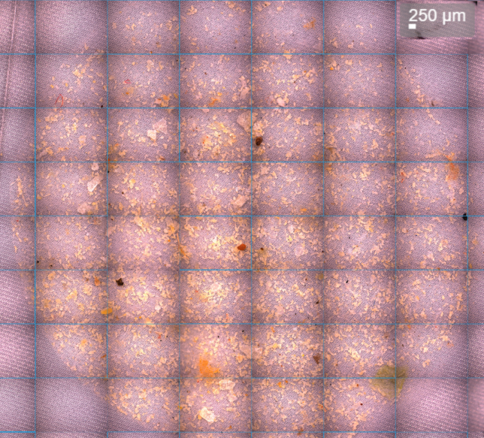
The overview/tile stitching facility lets us construct overviews of an entire membrane or ferrography slide. In the following overview we were able to use Dark Field illumination to successfully separate translucent particles from the woven 11µm membrane patch, which is also translucent.
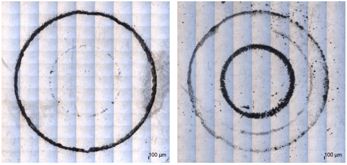
The following overviews show differences in large (inner ring) and fine (outer ring) particle densities in two ferrography samples.